After quite a few years, I finally managed to figure out how to put a Flysky FS-TH9X transmitter/receiver pair to good use, without putting it in the sky.
Quick question: If a project doesn’t run on the ground, and doesn’t get off the ground, where do you put it?
Answer: Underwater.
That’s precisely what I decided to do after figuring out that the cost of building a simple, stable drone (not necessarily a quadcopter) with a camera , would probably cross my budget by about 200%.
A word of caution to beginners: Don’t buy a transmitter unless you know for sure that the receiver or simulator is also available. It’s an obvious blunder and one that is extremely easy to make when the salesperson is as excited as you are.
Frankly, I couldn’t leave this ₹8000 piece of hardware sitting around, doing nothing! But when we bought it, I hadn’t the faintest clue how to use it outside the simulator software in the shop. They said that the software was out of stock and would come soon. Five years later, it’s still out of stock! Although the prospects of a project using the Flysky controller seemed bleak, I kept going back to check it out, time and again.
On 15th May 2019, after yet another week of research, I cobbled together a plan to steer an Unmanned Underwater Vehicle (UUV) using this very controller, through a technique called Thrust Vector Control (a.k.a. thrust vectoring or TVC).
Named in honour of Captain Nemo’s submarine from Jules Verne’s fiction novel ‘Twenty Thousand Leagues Under the Sea’, Nautilus is a remotely operated unmanned underwater vehicle, capable of transmitting a live video feed to the operator, taking photographs and saving recorded footage on-board.
From: 08.05.2019 – Design phase commencement
To: 05.06.2019 – Field test
Technical specifications: It’s Latin and G(r)eek!
It came as a bit of a surprise that one of the most important pages in the user manual (for wiring the receiver and transmitter) was entirely in Mandarin with no English translation! Moreover, the receiver’s BATT and BIND ports were both connected on the same pins, although the ports were labelled correctly. This turned out to be a manufacturing defect that all users with this controller, had experienced.
Apart from that minor hiccup, the FS-TH9X is a fantastic flight controller which has signal configurations for several servo arrangements, including those of RC gliders, aeroplanes, helicopters, quadcopter and even tricopters.

Most importantly, it has two 4-way joysticks which are essential for controlling thrust, pitch, roll and yaw.
Theory: Thrust Vector Control
- Thrust (Forward/Backward) – Left stick – up/down
- Yaw – Left stick – left/right
- Pitch – Right stick – up/down
- Roll – Right stick – left/right
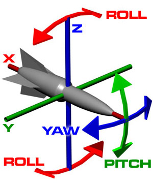
Cutting this down to the bare necessities for steering a slow moving vehicle in three dimensions without any fancy acrobatics, only the pitch and yaw controls are required. Thrust control is, of course, a prerequisite. Reversible thrust is an added advantage for easier maneuverability.
Resource Constraints
The UUV needed to be built in the shortest possible time-frame, (before school reopened) with minimum requirement of ordered parts. This automatically meant that keeping the receiver’s intermediate PPM signal processing system simple, was of paramount importance.
Design: The Good the Bad and the Ugly
Initial designing commenced on 8 May 2019, beginning with ‘the ugly’…

The next one almost made the cut, but for its requirement of metal geared servos controlling the dorsal and ventral fins.
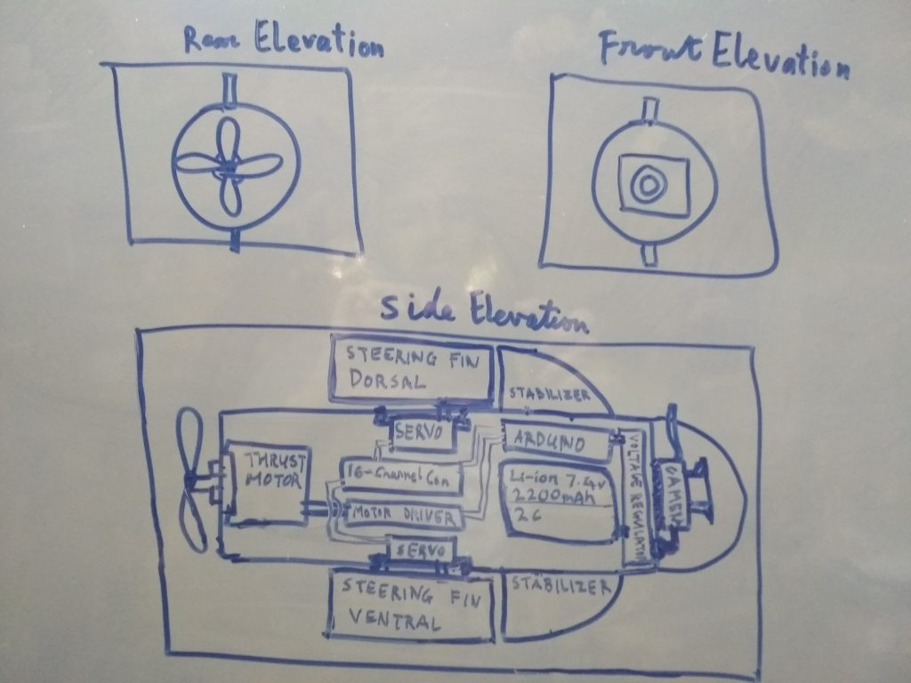
Eventually, the thrust vector control system was finalised, with no external fins, flaps or mountings, apart from a camera to document video footage.
Hardware

Thrust Propeller Arduino Nano (ATMEGA 328 AVR microcontroller) MOSFET based Dual DC Motor Driver Power Distribution and Reverse Voltage Protection Circuit Voltage Regulation Circuit (LM7806) Propeller Guard and Seal


Major Components
Due to afore-mentioned reasons, Nautilus was built primarily out of commercially available, standardised components. Apart from the receiver module which came along with the Flysky transmitter, other major standardised components include:
Propeller
Most standard propellers come with shafts of diameters no more than 3-4 mm, while my 12v DC Geared Motor had a 6 mm shaft. There was only one seller on amazon.in, who had advertised for an unconventional plastic propeller with a 6 mm shaft.
Upon receiving it, due to an error of less than a quarter of a millimetre, the propeller refused to fit over the shaft.
That’s when Mr. Chari’s bench drill press came to the rescue. Filing down the extra micrometers, he explained how a perpendicular through-hole in the motor shaft, had caused it to expand over the years. The amount of metal that drill shaved off was barely discernible, but it worked very well.
Thrust and Servo Motors
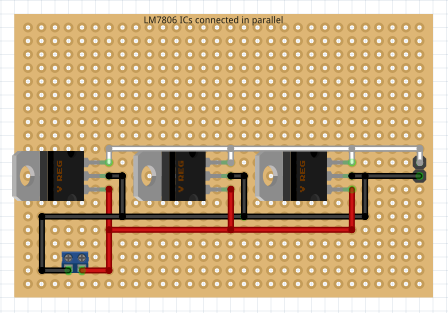
Over a fortnight of testing with and without micro-controllers attached to the receiver, I managed to put together a simple pan-tilt system of plastic servo motors which took their power supply from a home-made 6 volt 3 amp voltage regulation circuit (Three LM7806 ICs connected in parallel here). The PWM signal pins were directly connected to the receiver’s output channel for PPM signals.
Certain forums claim that there is a significant difference between the two, but personally, I didn’t find any difference in functionality… unless the manufacturers made another printing mistake.
Power Supply
Initially I was using a 12v 400 mA power adapter to test the system. However, after fluctuations in the PPM (Pulse Position Modulation) signals from the receiver due to insufficient current supply, I switched over to a set of three 3.7v 18650 Li-ion rechargeable cells (3800mAh), hooked up in series.
Voltage Regulator and Distributor
Making my own voltage regulation circuit turned out to be a good choice, since the current supply could increase rather sharply sometimes, due to the thruster’s mildly fluctuating current draw. However, I’ll be honest here: there isn’t any external reverse voltage protection, so it is still susceptible to human error if the user accidentally switches terminals while hooking up the battery,
Power distribution boards can be soldered together quite easily. Mine had a set of generic male double header pins on one end, running parallel to a set of generic female double header pins. Though non-essential, a distribution bus like this one provides a centralised point for power inputs and outputs, making the wiring much simpler to understand.
Software
Coded with the official Arduino IDE, the Arduino Nano’s programme decodes the PPM signals from the Flysky receiver, converts it to an understandable frequency and remaps it to PWM, sending the signal to the thruster only if it is above a minimum threshold.
It acts like a high-pass filter, preventing negligibly weak PWM signals from supplying insufficient power to the thrust motor.
If you feel like trying it out for yourself, here’s the code. Codes copied ditto have a habit of misfiring when tested on different hardware, so please tweak and remix it to your flavour before using it 🙂
int i,j,k,l,h, rawsig=0, PWM=0, dir=0;
float smoothfreq=0, freq=0;
float freqs[5]={0,0,0,0,0};

void setup()
{
  pinMode(A0, OUTPUT);
  analogWrite(A0, 0);delay(1);//short ground signal to lower all levels to normal
  pinMode(A0, INPUT);
  pinMode(A1, OUTPUT);
  analogWrite(A1, 0);delay(1);//short ground signal to lower all levels to normal
  pinMode(A1, INPUT);
  Serial.begin(9600);
  pinMode(9, OUTPUT);
  pinMode(4, OUTPUT);
  digitalWrite(4, LOW);//thruster direction defaults to forward
}

void loop()
{//Copyright http://raunakhede.com/

  smoothfreq=0;

  //Reading 0
  i=0;
  for(int timer=0; timer<1000; timer++)
  {
    rawsig=analogRead(A0);
    if(rawsig>0)
    {
      i++;
    }
    delayMicroseconds(0.1);
  }
   freqs[0] = i/100.0;

  //Reading 1
  j=0;
  for(int timer=0; timer<1000; timer++)
  {
    rawsig=analogRead(A0);
    if(rawsig>0)
    {
      j++;
    }
    delayMicroseconds(0.1);
  }
   freqs[1] = j/100.0;

  //Reading 2
  k=0;
  for(int timer=0; timer<1000; timer++)
  {
    rawsig=analogRead(A0);
    if(rawsig>0)
    {
      k++;
    }
    delayMicroseconds(0.1);
  }
   freqs[2] = k/100.0;

  //Reading 3
  l=0;
  for(int timer=0; timer<1000; timer++)
  {
    rawsig=analogRead(A0);
    if(rawsig>0)
    {
      l++;
    }
    delayMicroseconds(0.1);
  }
   freqs[3] = l/100.0;

  //obtained raw, mildly fluctuating signals

  //Now smoothen the fluctuations to get cleaner values before mapping
  smoothfreq = smoothen(freqs[0], freqs[1], freqs[2], freqs[3]);

  PWM = constrain(map(smoothfreq*100,0.53*100,1.01*100,0,255),0,255);//Remap to PWM compatible values

//Check the direction of rotation
  h=0;
  for(int timer=0; timer<1000; timer++)
  {
    if(analogRead(A1)>0)
    {
      h++;
    }
    delayMicroseconds(0.1);
  }
  dir = h/10.0;

//Set the direction of rotation
  if(dir>7)
  {
   digitalWrite(4, HIGH);
  }
  else
  {
    digitalWrite(4, LOW);
  }

//0.67 to 0.86 is mid-range=low power, above 0.86 is high power, and below 0.67 is off - as per smoothfreq
//Filters for different threshold values to adjust speed
  if(PWM<93)
  {
    analogWrite(9, 0);
  }
  else if(PWM>57 && PWM<93)
  {
    analogWrite(9, 0);
  }
  else if(PWM>93 && PWM<114)
  {
    analogWrite(9, 200);
  }
  else if(PWM>114 && PWM<166)
  {
    analogWrite(9, 220);
  }
  else if(PWM>166 && PWM<208)
  {
    analogWrite(9, 240);
  }
  else if(PWM>208 && PWM<249)
  {
    analogWrite(9, 255);
  }
  freq=smoothfreq;//sets the old frequency (freq) variable to the current frequency (smoothfreq)
}

float smoothen(float p, float q, float r, float s)
{
  return (p+q+r+s)/4;//takes the average of 4 values
}
Field Test
Tested at a construction site in Ribandar, Goa, this UUV performed very well in the first trial.
Nearly a meter long weighing in at about 3.5 kg, Nautilus easily floated on the surface. As per my calculations, it would require 5 kg of additional weight in order to attain neutral buoyancy, before making any plans of diving and resurfacing. It’s performance on the surface was, therefore, satisfactory.
The second trial involved adding a 1 kg dumbbell inside. It still floated, but with the thruster’s shaft dipping slightly below the waterline. After moving around a bit, I had a hunch that it may have sprung a leak.
Turns out, nearly a cupful of water had entered through the grease seal between the thrust motor’s shaft and C-ring.
This led me to make a list of corrections for Nautilus v2, for which I hope to begin work, sometime in the future.
Corrections
- Seal off the thrusters completely, isolating them in separate compartments from the main control systems and battery.
- Leave nothing but well insulated wires connecting systems between compartments.
- The number of moving/flexible seals is directly proportional to the probability of springing a leak. As far as possible, eliminate any moving seals or flexible covers.
Future additions
- Variable buoyancy system
- Oil seals on thruster shafts
- Brushless thrust motors
- Tripod design to accommodate three thrusters and no servos motors
Until the next version surfaces!